As part of of my plan to put a Dana 44 under the YJ wanted to go to a SOA high steer Setup. This would not only give good Flex and lift but would help fight bump steer and move the tie rod out of harms way. Since the Dana 44 I was using came off a 78 Chevy Blazer the left hand knuckle was already drill and dapped. However, the right side needed to be decked flat and drilled and tapped to allow attachment of a high steer arm. I looked at having the machine work done the local shop I went to estimated 2 hrs at $60/hr. and could not guaranty that it would not take longer. I looked at sending the Knuckle to one of the many Outfits online that offer to machine knuckles but they wanted at least $50 and I would have to pay shipping both ways. Living in Alaska this would place the total price well over $100. Fortunately for me I have learned a bit of machining and had access to a old BridgePort mill. Not only would doing this job myself save me some money, but it would also allow me to brag just a little:-)
This write up is NOT A HOW TO ON RUNNING A MILL. Many important safety practices are not mentioned here, If you are not competent at running a milling machine then this will not help you. Anything you do, don't do, or think about as a result of reading this is YOUR REASONABILITY and yours alone. This write-up is for information purposes only, and do not show proper safety or design considerations that must be considered.
Step 1: Research
I spent many hours on the net researching high steer arms and knuckles. The following are links to some of the better info I found.
Mr. N's Dana 44 Flat Top Knuckle and High Steer info: This is by far the best information on flat top knuckles.
http://77cj.littlekeylime.com/flatop_knucles.html
This Page on the POR web page was also very helpful.
http://www.pirate4x4.com/tech/billavista/Steering/Steering_Index/SteeringIndex.htm
 I do not remember where I downloaded this from
but it was very helpful in laying out the holes to be Drilled.
I do not remember where I downloaded this from
but it was very helpful in laying out the holes to be Drilled.
Step 2: Setup
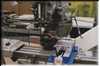
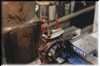
 First off a Picture of the Mill. This mill has seen better years
and was made in 1964. The whole Process would have
been much easier if it had a Digital Read
Out (DRO) setup, but no big deal.
First off a Picture of the Mill. This mill has seen better years
and was made in 1964. The whole Process would have
been much easier if it had a Digital Read
Out (DRO) setup, but no big deal.
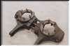
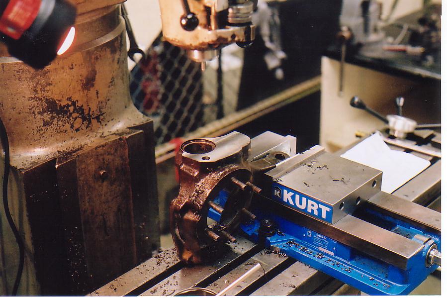
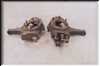 Here is a (before) picture of the Drivers side knuckle (factory
machined) next to the Passenger side (not machined). The first
thing I did was grab a set of calipers and confirm that the lay out
picture form step 1 matched the driver side knuckle. It did.
Here is a (before) picture of the Drivers side knuckle (factory
machined) next to the Passenger side (not machined). The first
thing I did was grab a set of calipers and confirm that the lay out
picture form step 1 matched the driver side knuckle. It did.
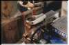
It often seems that for every minute of actual cutting I spend 15 minutes to an hour on setup. The first thing that needs to be done is find away to mount the knuckle on the mill table such that it can't move or vibrate. I need to mount it such that the top needing to be machined flat was parallel to the surface of the table. I also wanted the spindle mounting surface was parallel to the x-axis of motion on the mill. This would allow me to measure measure the dimensions for the bolt holes with the x and y-axis with out having to rotate my coordinate system. After inspecting the driver side Knuckle I found that the top was machined parallel to the bottom. This meant that all I needed to do was bolt the Knuckle down through the lower ball joint whole and it would be in the correct location for milling the top flat.
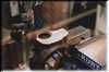
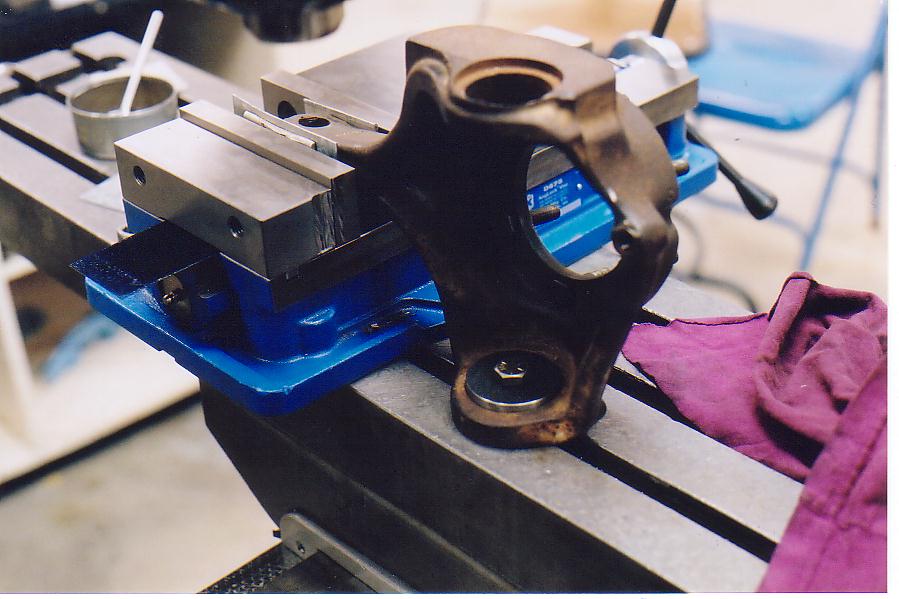
 To
do this I went to the lathe and made a puck of the correct diameter to
just fit in the step where the lower ball joint sits. Here it is
bolted to the mill. The bolt head you see treads down into a T
nut in the table. I still needed to prevent the knuckle from
rotating and hold it so that the spindle mounting surface was parallel
to the x-axis. To do this I clamped the cast arm on the
knuckle in the vice and added shims to rotate to the correct position.
To
do this I went to the lathe and made a puck of the correct diameter to
just fit in the step where the lower ball joint sits. Here it is
bolted to the mill. The bolt head you see treads down into a T
nut in the table. I still needed to prevent the knuckle from
rotating and hold it so that the spindle mounting surface was parallel
to the x-axis. To do this I clamped the cast arm on the
knuckle in the vice and added shims to rotate to the correct position.
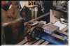
 Here I am using a tea clock indicator to check that the spindle
mounting surface is parallel to the x-axis. All the tea clock
indicator does is show a change in position. By mounting it to
the spindle on the mill (not moving) and moving the table (with knuckle
attached) in the x-axis (left to right) I can if it is parallel as
desired. If the reading does not change it must be
parallel. Note, the sheet metal used as a shim (to rotate the
knuckle) sitting on the right side of the vice.
Here I am using a tea clock indicator to check that the spindle
mounting surface is parallel to the x-axis. All the tea clock
indicator does is show a change in position. By mounting it to
the spindle on the mill (not moving) and moving the table (with knuckle
attached) in the x-axis (left to right) I can if it is parallel as
desired. If the reading does not change it must be
parallel. Note, the sheet metal used as a shim (to rotate the
knuckle) sitting on the right side of the vice.
 Here is a better picture of the shims. After 3 tries I got the
knuckle within 0.001" in 3" of parallel, and called it close
enough. I then double checked that everything was tight and ready
to go.
Here is a better picture of the shims. After 3 tries I got the
knuckle within 0.001" in 3" of parallel, and called it close
enough. I then double checked that everything was tight and ready
to go.
Part 3: Decking the surface flat
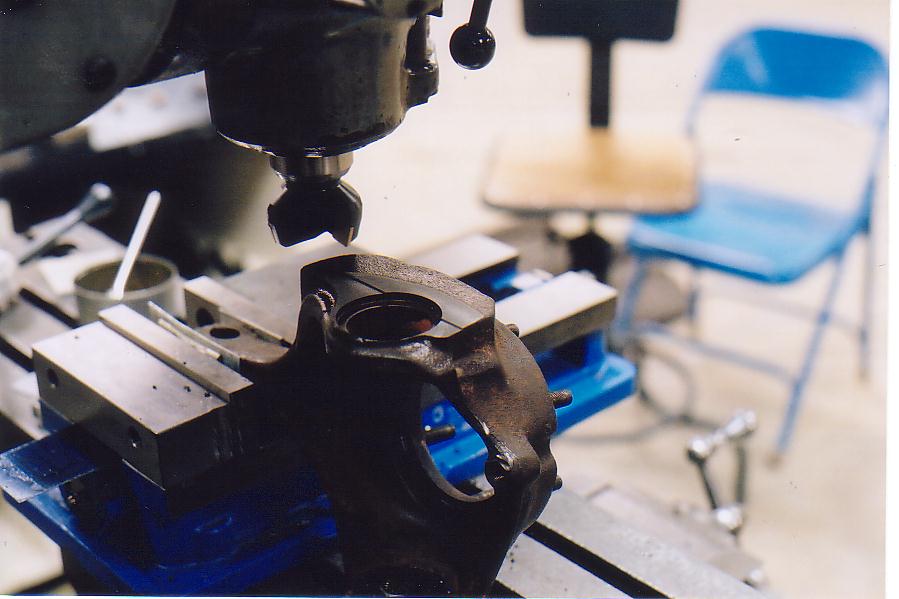
 The first actual cutting is to flatten the top. Here is the index
able carbide cutter after one of the intermediate passes (sorry about
the poor lighting). I was a little worried about vibration
because I was cutting so far from the table and so took small amounts
0.015" off at a time. However, it turned out to be a very solid
setup.
The first actual cutting is to flatten the top. Here is the index
able carbide cutter after one of the intermediate passes (sorry about
the poor lighting). I was a little worried about vibration
because I was cutting so far from the table and so took small amounts
0.015" off at a time. However, it turned out to be a very solid
setup.
 Here the top is Decked flat and ready for drilling.
Part 4: Locating the Knuckle In a coordinate system
The next thing to do was to pick up the center of the upper ball joint hole with the dials on the table. this Allows the holes to be drilled in exact positions relative to the ball joint hole. Note: all measurements are based off of this hole see drawing in part 1. I used a edge finder to locate the sides of the ball joint hole and adjusted the dials till the center was at x= 0.000", y=0.000". This part would have been much much easier with a DRO on the mill but we use what we have. Sorry no pictures of this part.
 Next it is just a mater of moving the table using the dials
(remembering Backlash) and drilling the first hole. I used a 1/8"
bit as a pilot hole and then followed with a 1/2". Here the hole
has been drilled and is waiting for taping. The holes need to be
taped for 9/16"-18 threads, which calls for a hole of 33/64".
However, I did not have that size I was considering getting one until I
consulted a Machinists handbook and found that drilling with a 33/64
resulted in a standard 75% thread. However, but drilling with a
1/2" the resulting tread would be 100% depth. This would be
stronger and I would not have to buy a drill that I would likely never
need again (luckily a friend had a tap).
Next it is just a mater of moving the table using the dials
(remembering Backlash) and drilling the first hole. I used a 1/8"
bit as a pilot hole and then followed with a 1/2". Here the hole
has been drilled and is waiting for taping. The holes need to be
taped for 9/16"-18 threads, which calls for a hole of 33/64".
However, I did not have that size I was considering getting one until I
consulted a Machinists handbook and found that drilling with a 33/64
resulted in a standard 75% thread. However, but drilling with a
1/2" the resulting tread would be 100% depth. This would be
stronger and I would not have to buy a drill that I would likely never
need again (luckily a friend had a tap).
 Here the hole is being tapped. This picture needs some
explanation. Note, the spindle on the mill has a center in it
that is being pushed into the hole in the back of the tap. This
does three things. First it starts the tap straight in the
hole. This is extremely important as I am taping about 1" in
depth and the slightest misalignment would prevent the hole from
taping. Second it helps the tap start by giving it an even
downward force. And Third it prevents side load from turning the
tap from binding the tap in the treads and potentially causing it to
brake. The wrench used to turn the tap can hardly be seen here.
Here the hole is being tapped. This picture needs some
explanation. Note, the spindle on the mill has a center in it
that is being pushed into the hole in the back of the tap. This
does three things. First it starts the tap straight in the
hole. This is extremely important as I am taping about 1" in
depth and the slightest misalignment would prevent the hole from
taping. Second it helps the tap start by giving it an even
downward force. And Third it prevents side load from turning the
tap from binding the tap in the treads and potentially causing it to
brake. The wrench used to turn the tap can hardly be seen here.
 Here the first hole is taped and the center has been replaced with a
1/8" bit ready to move to the next hole. Note, the pretty treads.
Here the first hole is taped and the center has been replaced with a
1/8" bit ready to move to the next hole. Note, the pretty treads.
 Here the first 2 are taped and the third is drilled and ready to tap.
Part 5: Checking/ Admiring Work
 All done. The treads came out very well I was some what worried
that it would be hard to tap the 100% treads but the Tap was very sharp
and the treads cut easy and look good.
All done. The treads came out very well I was some what worried
that it would be hard to tap the 100% treads but the Tap was very sharp
and the treads cut easy and look good.
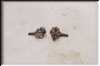
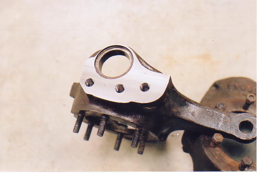
 Here I place the studs on the drivers side next to the holes in the
passengers side to check that the holes are in fact in the right
place. Dead on Yippee!!!!
Here I place the studs on the drivers side next to the holes in the
passengers side to check that the holes are in fact in the right
place. Dead on Yippee!!!!
 After Picture. In the end it took about 4 hrs. to do the whole
job. However, I moved very slow and double checked
everything. With DRO's on the mill and the experience of having
done one, I cold likely repeat this in one to one and a half
hours. So the $50 that shops online want for this is very fare.
After Picture. In the end it took about 4 hrs. to do the whole
job. However, I moved very slow and double checked
everything. With DRO's on the mill and the experience of having
done one, I cold likely repeat this in one to one and a half
hours. So the $50 that shops online want for this is very fare.
I spent many hours on the net researching high steer arms and knuckles. The following are links to some of the better info I found.
Mr. N's Dana 44 Flat Top Knuckle and High Steer info: This is by far the best information on flat top knuckles.
http://77cj.littlekeylime.com/flatop_knucles.html
This Page on the POR web page was also very helpful.
http://www.pirate4x4.com/tech/billavista/Steering/Steering_Index/SteeringIndex.htm
 I do not remember where I downloaded this from
but it was very helpful in laying out the holes to be Drilled.
I do not remember where I downloaded this from
but it was very helpful in laying out the holes to be Drilled. Step 2: Setup
 First off a Picture of the Mill. This mill has seen better years
and was made in 1964. The whole Process would have
been much easier if it had a Digital Read
Out (DRO) setup, but no big deal.
First off a Picture of the Mill. This mill has seen better years
and was made in 1964. The whole Process would have
been much easier if it had a Digital Read
Out (DRO) setup, but no big deal.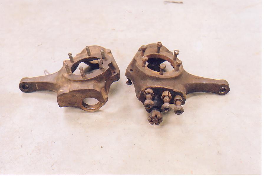 Here is a (before) picture of the Drivers side knuckle (factory
machined) next to the Passenger side (not machined). The first
thing I did was grab a set of calipers and confirm that the lay out
picture form step 1 matched the driver side knuckle. It did.
Here is a (before) picture of the Drivers side knuckle (factory
machined) next to the Passenger side (not machined). The first
thing I did was grab a set of calipers and confirm that the lay out
picture form step 1 matched the driver side knuckle. It did.It often seems that for every minute of actual cutting I spend 15 minutes to an hour on setup. The first thing that needs to be done is find away to mount the knuckle on the mill table such that it can't move or vibrate. I need to mount it such that the top needing to be machined flat was parallel to the surface of the table. I also wanted the spindle mounting surface was parallel to the x-axis of motion on the mill. This would allow me to measure measure the dimensions for the bolt holes with the x and y-axis with out having to rotate my coordinate system. After inspecting the driver side Knuckle I found that the top was machined parallel to the bottom. This meant that all I needed to do was bolt the Knuckle down through the lower ball joint whole and it would be in the correct location for milling the top flat.
 To
do this I went to the lathe and made a puck of the correct diameter to
just fit in the step where the lower ball joint sits. Here it is
bolted to the mill. The bolt head you see treads down into a T
nut in the table. I still needed to prevent the knuckle from
rotating and hold it so that the spindle mounting surface was parallel
to the x-axis. To do this I clamped the cast arm on the
knuckle in the vice and added shims to rotate to the correct position.
To
do this I went to the lathe and made a puck of the correct diameter to
just fit in the step where the lower ball joint sits. Here it is
bolted to the mill. The bolt head you see treads down into a T
nut in the table. I still needed to prevent the knuckle from
rotating and hold it so that the spindle mounting surface was parallel
to the x-axis. To do this I clamped the cast arm on the
knuckle in the vice and added shims to rotate to the correct position. Here I am using a tea clock indicator to check that the spindle
mounting surface is parallel to the x-axis. All the tea clock
indicator does is show a change in position. By mounting it to
the spindle on the mill (not moving) and moving the table (with knuckle
attached) in the x-axis (left to right) I can if it is parallel as
desired. If the reading does not change it must be
parallel. Note, the sheet metal used as a shim (to rotate the
knuckle) sitting on the right side of the vice.
Here I am using a tea clock indicator to check that the spindle
mounting surface is parallel to the x-axis. All the tea clock
indicator does is show a change in position. By mounting it to
the spindle on the mill (not moving) and moving the table (with knuckle
attached) in the x-axis (left to right) I can if it is parallel as
desired. If the reading does not change it must be
parallel. Note, the sheet metal used as a shim (to rotate the
knuckle) sitting on the right side of the vice. 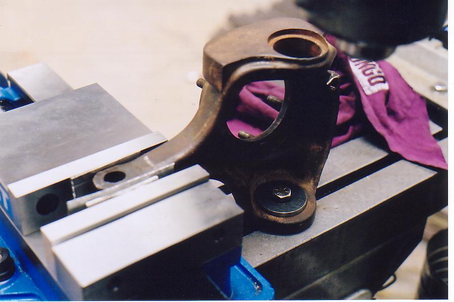 Here is a better picture of the shims. After 3 tries I got the
knuckle within 0.001" in 3" of parallel, and called it close
enough. I then double checked that everything was tight and ready
to go.
Here is a better picture of the shims. After 3 tries I got the
knuckle within 0.001" in 3" of parallel, and called it close
enough. I then double checked that everything was tight and ready
to go.Part 3: Decking the surface flat
 The first actual cutting is to flatten the top. Here is the index
able carbide cutter after one of the intermediate passes (sorry about
the poor lighting). I was a little worried about vibration
because I was cutting so far from the table and so took small amounts
0.015" off at a time. However, it turned out to be a very solid
setup.
The first actual cutting is to flatten the top. Here is the index
able carbide cutter after one of the intermediate passes (sorry about
the poor lighting). I was a little worried about vibration
because I was cutting so far from the table and so took small amounts
0.015" off at a time. However, it turned out to be a very solid
setup.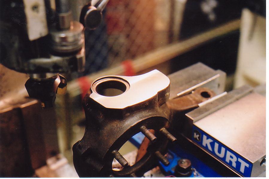 Here the top is Decked flat and ready for drilling.
Part 4: Locating the Knuckle In a coordinate system
The next thing to do was to pick up the center of the upper ball joint hole with the dials on the table. this Allows the holes to be drilled in exact positions relative to the ball joint hole. Note: all measurements are based off of this hole see drawing in part 1. I used a edge finder to locate the sides of the ball joint hole and adjusted the dials till the center was at x= 0.000", y=0.000". This part would have been much much easier with a DRO on the mill but we use what we have. Sorry no pictures of this part.
 Next it is just a mater of moving the table using the dials
(remembering Backlash) and drilling the first hole. I used a 1/8"
bit as a pilot hole and then followed with a 1/2". Here the hole
has been drilled and is waiting for taping. The holes need to be
taped for 9/16"-18 threads, which calls for a hole of 33/64".
However, I did not have that size I was considering getting one until I
consulted a Machinists handbook and found that drilling with a 33/64
resulted in a standard 75% thread. However, but drilling with a
1/2" the resulting tread would be 100% depth. This would be
stronger and I would not have to buy a drill that I would likely never
need again (luckily a friend had a tap).
Next it is just a mater of moving the table using the dials
(remembering Backlash) and drilling the first hole. I used a 1/8"
bit as a pilot hole and then followed with a 1/2". Here the hole
has been drilled and is waiting for taping. The holes need to be
taped for 9/16"-18 threads, which calls for a hole of 33/64".
However, I did not have that size I was considering getting one until I
consulted a Machinists handbook and found that drilling with a 33/64
resulted in a standard 75% thread. However, but drilling with a
1/2" the resulting tread would be 100% depth. This would be
stronger and I would not have to buy a drill that I would likely never
need again (luckily a friend had a tap).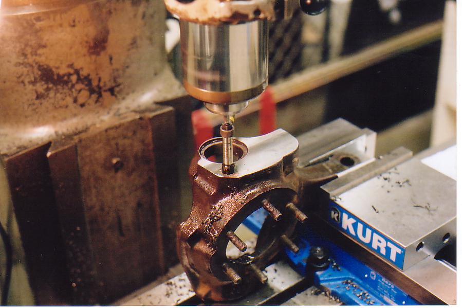 Here the hole is being tapped. This picture needs some
explanation. Note, the spindle on the mill has a center in it
that is being pushed into the hole in the back of the tap. This
does three things. First it starts the tap straight in the
hole. This is extremely important as I am taping about 1" in
depth and the slightest misalignment would prevent the hole from
taping. Second it helps the tap start by giving it an even
downward force. And Third it prevents side load from turning the
tap from binding the tap in the treads and potentially causing it to
brake. The wrench used to turn the tap can hardly be seen here.
Here the hole is being tapped. This picture needs some
explanation. Note, the spindle on the mill has a center in it
that is being pushed into the hole in the back of the tap. This
does three things. First it starts the tap straight in the
hole. This is extremely important as I am taping about 1" in
depth and the slightest misalignment would prevent the hole from
taping. Second it helps the tap start by giving it an even
downward force. And Third it prevents side load from turning the
tap from binding the tap in the treads and potentially causing it to
brake. The wrench used to turn the tap can hardly be seen here.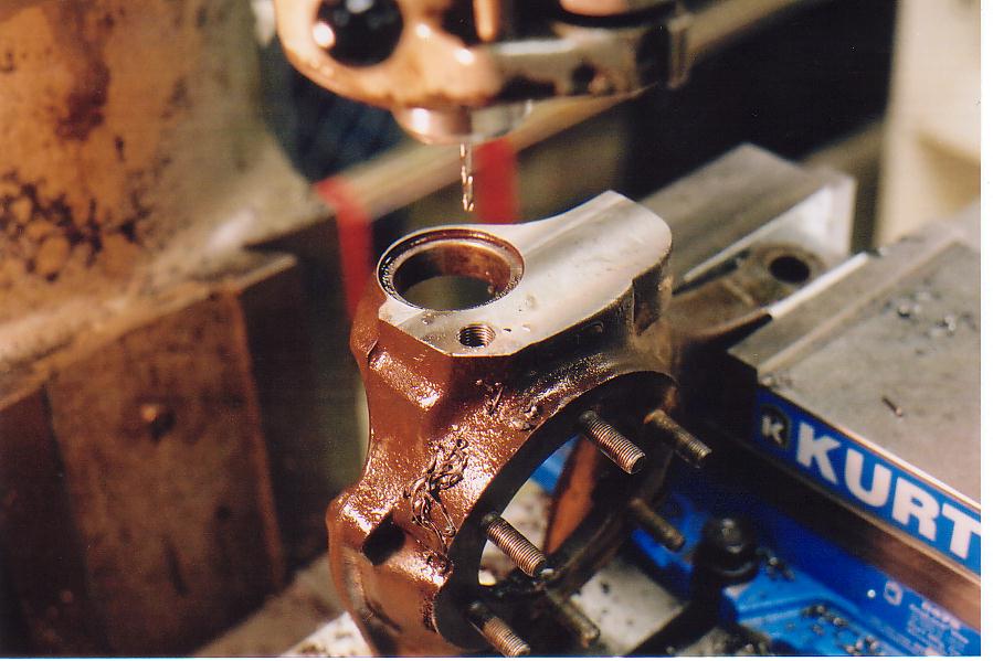 Here the first hole is taped and the center has been replaced with a
1/8" bit ready to move to the next hole. Note, the pretty treads.
Here the first hole is taped and the center has been replaced with a
1/8" bit ready to move to the next hole. Note, the pretty treads.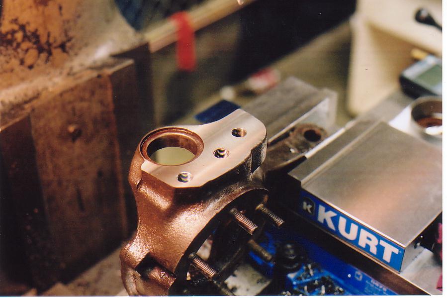 Here the first 2 are taped and the third is drilled and ready to tap.
Part 5: Checking/ Admiring Work
 All done. The treads came out very well I was some what worried
that it would be hard to tap the 100% treads but the Tap was very sharp
and the treads cut easy and look good.
All done. The treads came out very well I was some what worried
that it would be hard to tap the 100% treads but the Tap was very sharp
and the treads cut easy and look good.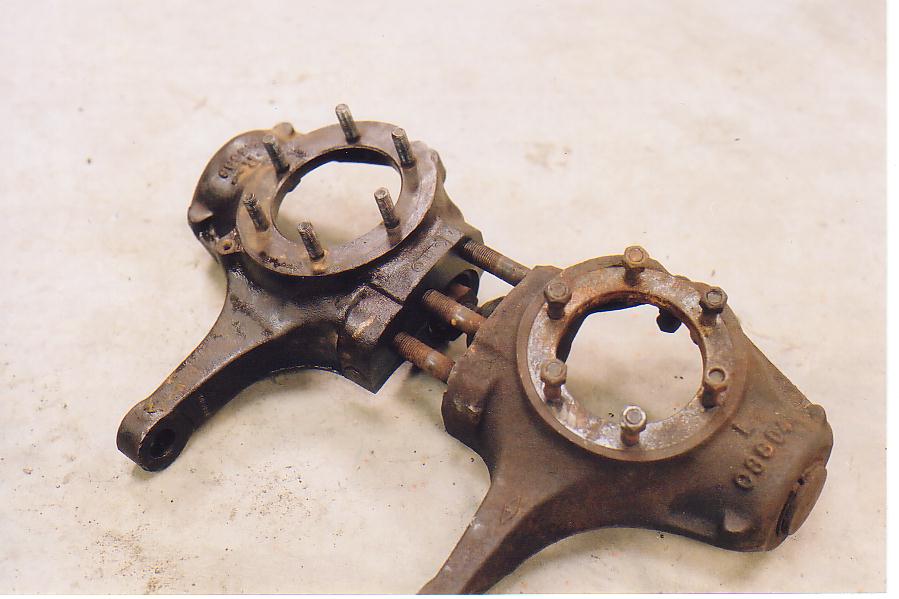 Here I place the studs on the drivers side next to the holes in the
passengers side to check that the holes are in fact in the right
place. Dead on Yippee!!!!
Here I place the studs on the drivers side next to the holes in the
passengers side to check that the holes are in fact in the right
place. Dead on Yippee!!!!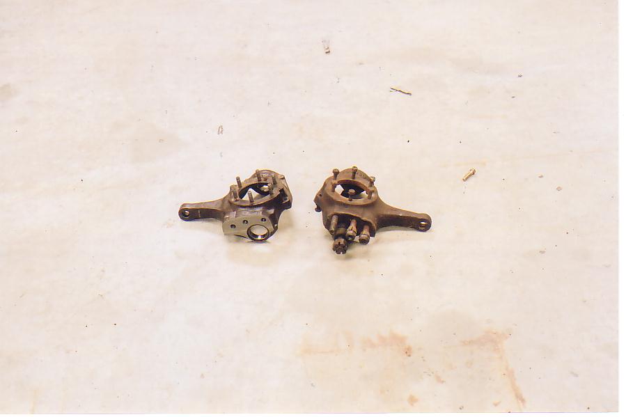 After Picture. In the end it took about 4 hrs. to do the whole
job. However, I moved very slow and double checked
everything. With DRO's on the mill and the experience of having
done one, I cold likely repeat this in one to one and a half
hours. So the $50 that shops online want for this is very fare.
After Picture. In the end it took about 4 hrs. to do the whole
job. However, I moved very slow and double checked
everything. With DRO's on the mill and the experience of having
done one, I cold likely repeat this in one to one and a half
hours. So the $50 that shops online want for this is very fare.